Even if the PDF is a scan, I can read the information I need.
The price is affordable and the service (mail sending) is very fast.
Thanks ! Regards. William (Fan of Kenwood)
Excellent just what I needed to replace the electrolytic caps and make this old gem a beauty again. Was as scan of the original photocopied service manual.
It was helpful to get schematic with waveforms in important points and lot of service information. Manual is good quality, fast delivered. Of course it is hardcopy of paper one with all its disadvantages.
Text excerpt from page 8 (click to view)
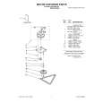
STANDARD NOTES FOR SERVICING
Circuit Board Indications
a. The output pin of the 3 pin Regulator ICs is indicated as shown. (2) Remove the flat pack-IC with tweezers while applying the hot air. (3) Bottom of the flat pack-IC is fixed with glue to the CBA; when removing entire flat pack-IC, first apply soldering iron to center of the flat pack-IC and heat up. Then remove (glue will be melted). (Fig. S-1-6) (4) Release the flat pack-IC from the CBA using tweezers. (Fig. S-1-6)
Top View Out In Input
Bottom View
b. For other ICs, pin 1 and every fifth pin are indicated as shown.
Caution:
1. Do not supply hot air to the chip parts around the flat pack-IC for over 6 seconds because damage to the chip parts may occur. Put masking tape around the flat pack-IC to protect other parts from damage. (Fig. S-1-2) 2. The flat pack-IC on the CBA is affixed with glue, so be careful not to break or damage the foil of each pin or the solder lands under the IC when removing it.
Hot-air Flat Pack-IC Desoldering Machine
5 Pin 1
10
c. The 1st pin of every male connector is indicated as shown.
Pin 1
CBA
How to Remove / Install Flat Pack-IC
1. Removal
With Hot-Air Flat Pack-IC Desoldering Machine: (1) Prepare the hot-air flat pack-IC desoldering machine, then apply hot air to the Flat Pack-IC (about 5 to 6 seconds). (Fig. S-1-1)
Masking Tape Tweezers Fig. S-1-2 Flat Pack-IC